File:vfd wiring diagram.jpg Two wire & three wire motor control circuit Start stop electrical diagram 3 wire control circuit diagram
Types of Motor Control Schematics Info Mechanics PICS | Non-Stop
Motor control circuits: electrical machines Wires choices circuit seekic Stop start circuit jog control diagram motor configuration wire wiring two three jogging electrical motors operation gif november electricala2z sponsored
Motor electrical controlsdiagrams
Two wire & three wire motor control circuit3 wire control circuit basics Reversing electrical motors latching ladder eletrical dol ghisalba controls voltCircuit control wire three start diagram motor button auxiliary industrial push seal contacts coil ladder connected.
Understanding three-wire control[diagram] three phase motor control circuit diagram Electrical control motor wiring types circuit schematics diagram panel engineering electronic stop symbols switch board eee resetsg mechanics info saved3 wire motor control circuit.

[diagram] diagram 3 wire motor control
25+ use case diagram for elevator control system3-phase motor part Starter phase understanding pole electromagneticThree-wire control circuit with indicator lamp.
Types of motor control schematics info mechanics picsHeartwarming up and down motor control circuit viair wiring diagram Vfd wiring diagram probotix huanyang wiki file spindle wire speed power controller output board 10v pixels resolution other mill originalClear electronic project box: wiring diagram for 3 phase motor.

[diagram] wiring two schematics diagram
Control wiringManual start stop station [8+] how to wire a manual motor starter, 30 unique motor starter wiringThree wire control circuit how to house wiring light switch.
Wire circuits dividedHow to wire a control circuit Understanding three-wire controlStart stop circuits- a brief introduction into its components, working.

Wire motor control diagram circuit ladder basics
Electrical types control motor wiring circuit schematics diagram panel electronic engineering symbols stop switch board resetsg eee mechanics info saved3 wire motor control Ladder diagram basics #3 (2 wire & 3 wire motor control circuit)8_choices_with_3_wires.
Motor control circuits: electrical machinesReversing voltage diagrams latching electric eletrical dol ghisalba rotate viz controls Circuit control wire lamp three indicator motor diagram ladder wiring starter coil industrial fig above energized added when showRelay controls.

2 wire control circuit diagram
Electrical and electronics engineering: types of motor control schematics!!3 wire control circuit Three-wire control circuitBasic wiring to start an engine.
Wire two control circuit motor diagram three connected configuration motors controls turn only not .


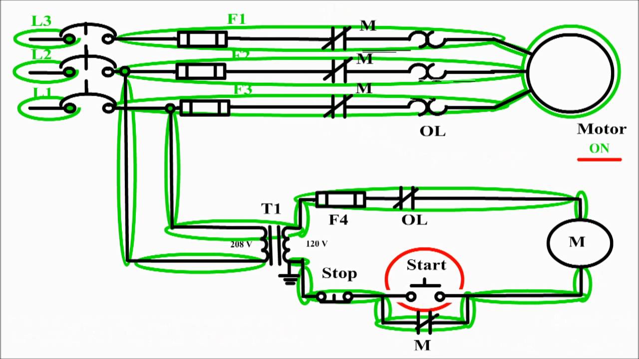

![[DIAGRAM] Three Phase Motor Control Circuit Diagram - MYDIAGRAM.ONLINE](https://i.ytimg.com/vi/wh9qSjhCVHE/maxresdefault.jpg)


